Controllers
Control our modulators with predetermined or streaming data
Cosmo (Predetermined Data Controller)
Features
- Supports evaluation and testing of all modules
- Generates multiple test patterns to the module
- Custom test patterns
- Configures GLV® Module parameters
- Operates as master or slave for synchronization of GLV® images to user equipment
Description
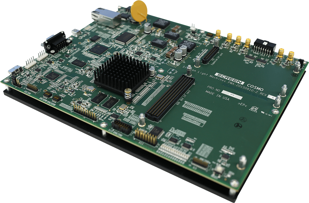
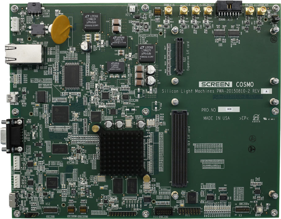
Cosmo is a custom designed single board computer utilizing an embedded ARM processor and a FPGA. The Cosmo Board can support all GLV®, PLV™ and DPM™ Modules by selecting an appropriate daughter card.
The Cosmo features a LVDS interface to send pixel data to the module at the full maximum column rate. An I2C interface allows the test board to initialize and configure the module for operation. An RS-232 serial interface allows the user to control the module with a PC HyperTerminal using parametrized ASCII commands. In addition, a USB-3 interface is provided that allows the user to download large custom test patterns to the Cosmo’s pixel memory. A GUI based “Pixel Download Tool” is available for ease of use.
User Interfaces
| RS-232 | Provides user control using parametrized ASCII commands (115,200 baud) |
|---|---|
| USB3 | For downloading user defined pixel data to Cosmo’s pixel memory |
| Ethernet | Allows in-the-field firmware upgrades of the Cosmo ARM processor & FPGA |
| Trigger In | Column and frame trigger inputs |
| Trigger Out | Column and frame trigger outputs |
| Power Input | Cosmo test board: 24 VDC |
Specifications
| Column Rate | 350 kHz (max, module dependent) |
|---|---|
| Pixel Memory | 65k–130k columns or frames (module dependent) |
Application Software
Allows a user to define many columns of custom GLV® pixel data in a spreadsheet (.csv format). The Pixel Download Program will read the pixel data from the spreadsheet and download the pixel data to memory on the Cosmo Test Board. ASCII commands can be used to control the sequencer on the Cosmo that reads the memory and sends the data to the GLV® Module at up to the maximum column rate.
SC100 Streaming Controller for GLV® and P1088-HS
Features
- Streaming Controller for GLV® and P1088-HS.
- Allows user to send pixel data to GLV® module via PCIe interface during run time.
- Operates as master or slave for synchronization of GLV® images to user equipment.
- API Libraries provided for Windows and Linux
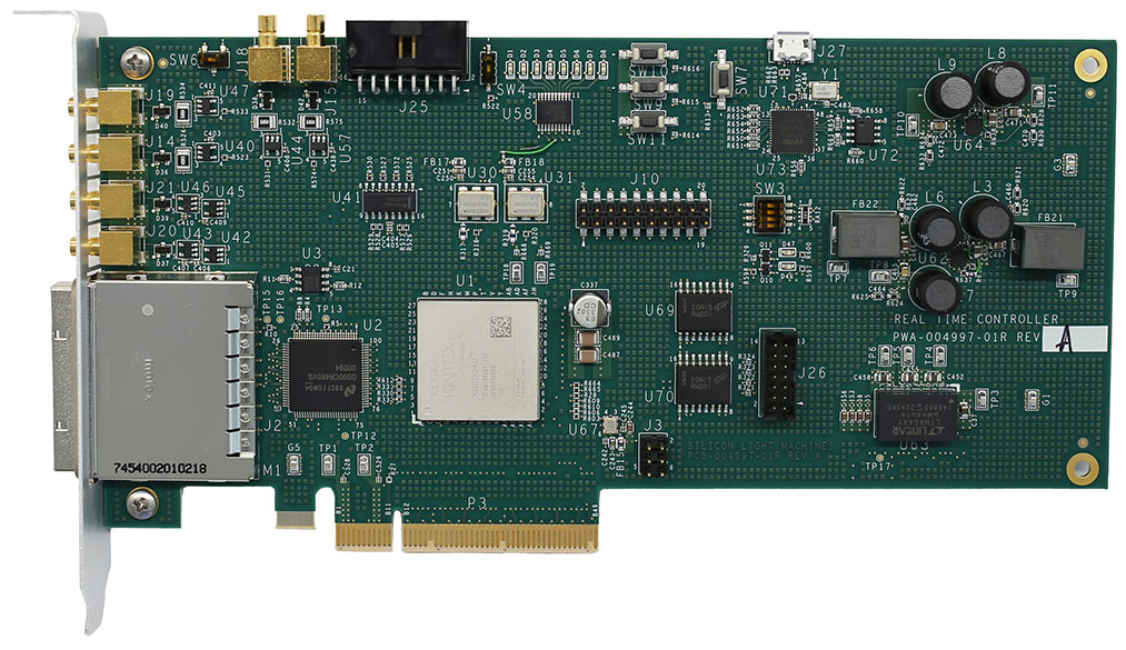
Description
The Streaming Controller is a GLV® controller card utilizing FPGA and LVDS interface chip to send pixel data to the GLV® module. The FPGA is customized with a PCIe Interface, embedded dual-port memory and a GLV® interface. The PCIe interface can write to the dual-port memory while the internal sequencer is reading the memory and sending the pixel data to the GLV®. Each line update can be synchronized with an external or internal trigger. The internal sequencer can loop through all (or subset of) lines in memory. The sequencer can be programmed for a finite number of loops or run continuously until stopped. The sequencer can send pixel data from the dual-port memory to the GLV® at the maximum col rate. The high bandwidth PCIe interface along with the dual-port pixel memory opens opportunities to some real time applications.
User Interfaces
| PCIe Gen3 x 4 | For writing pixel data to the Controller’s pixel memory & for control over the module |
|---|---|
| Trigger In | Column & Frame trigger inputs |
| Trigger Out | Column & Frame trigger outputs |
| Power Input | No extra power supply needed. Powered through the PC. |
Specifications
| Modulation Frequency | Refer to module spec |
|---|---|
| Pixel Memory | 512 set of pixel data** |
| Propagation Delay | 20μs* |
| Minimum Delay between PCIe Transaction | 1ms* |
* Tested with an OS, it can be shortened if you can send directly via PCIe without an OS in the loop.
**A version with two external DDR4 memory version is also available.
Application Software
Windows and Linux API Libraries are provided for initializing the GLV® module and writing pixel data to the GLV® module
SC200 Streaming Controller for PLV™ and DPM™
Features
- Streaming Controller for PLV™
- Allows user to send pixel data to PLV™ module via PCIe interface during run time.
- Operates as master or slave for synchronization of PLV™ images to user equipment.
- API Libraries provided for Windows and Linux
Description
The Streaming Controller is a PLV™ controller card utilizing FPGA and LVDS interface chip to send pixel data to the PLV™ module. The FPGA is customized with a PCIe Interface, two external DDR4 memory banks and a PLV™ interface. The PCIe interface can write into one of the DDR4 memory bank while the internal sequencer is reading memory from the other and sending the pixel data to the PLV™. Each line update can be synchronized with an external or internal trigger. The internal sequencer can loop through all (or subset of) lines in memory. The sequencer can be programmed for a finite number of loops or run continuously until stopped. The sequencer can send pixel data from the DDR4 memory to the PLV™ at the maximum col rate. The high bandwidth PCIe interface along with the dual DDR4 memory pixel memory bank opens opportunities to some real time applications.

User Interfaces
| PCIe Gen3 x 4 | For writing pixel data to the Controller’s pixel memory & for control over the module |
|---|---|
| Trigger In | Column & Frame trigger inputs |
| Trigger Out | Column & Frame trigger outputs |
| Power Input | No extra power supply needed. Powered through the PC. |
Specifications
| Modulation Frequency | Refer to module spec |
|---|---|
| Pixel Memory | 256k set of pixel data per bank |
| Propagation Delay | 20μs* |
| Minimum Delay between PCIe Transaction | 1ms* |
* Tested with an OS, it can be shortened if you can send directly via PCIe without an OS in the loop.
Application Software
Windows and Linux API Libraries are provided for initializing the PLV™ module and writing pixel data to the PLV™ module